

Flush Port Reroute Installation Guide
See what’s involved before you purchase or begin installation. This general overview covers the parts you’ll need, the installation process, and when to involve a qualified marine technician.
15 steps · Read the entire guide before starting.
Before you begin
Professional guidance is recommended.
Installation varies by engine brand, model, year, and vessel. Some installations are straightforward; others require a qualified marine technician.
If you do not understand any step, stop and seek professional installation.
Cutting into your boat or engine plumbing can cause damage or injury. Consult your engine and vessel manufacturers’ instructions and a qualified marine professional before making modifications. This guide, its diagrams, photos, and video provide a general overview only. They do not establish fitment or replace the instructions for your specific engine and vessel.
The installer is responsible for confirming compatibility, choosing the correct connection point, and completing and testing the installation safely. To the extent permitted by applicable law, Seamule, LLC / Flushmaster is not responsible for damage or injury caused by improper installation, incompatible modifications, or failure to follow manufacturer instructions. This notice does not exclude liability that cannot legally be excluded.
Secure the boat and prevent accidental engine starting before work. Check behind every drilling or cutting location for hoses, wiring, and other obstructions. Follow manufacturer requirements for fasteners and sealing cut surfaces.
If instructions are unclear, unavailable, or conflict, stop. Have your engine’s authorized service center or a qualified marine technician confirm the correct procedure before continuing. Confirm manufacturer requirements, including any warranty conditions, before making modifications.
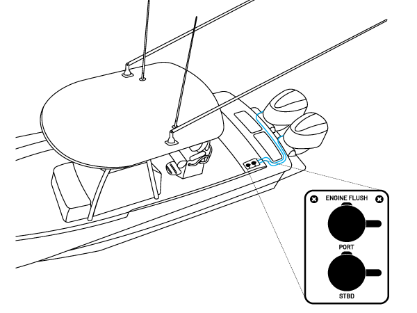
How the reroute connects
A separate hose runs from each engine’s flush line to its own connection on the plate. The blue lines show the hose routes.
The enlarged plate detail shows the individual port and starboard connections, accessible inside the boat.
Layout overview only. Actual hose routing and engine connection points vary.
Match the parts to your engines
Choose one Flush Port Reroute with an outlet for each engine, plus one Reroute Install Kit per engine.
Confirm compatibility before ordering: Outlet count alone does not establish fitment. Have a qualified marine technician verify the engine connection method and the hose and fitting sizes required for your setup.
Single engine
(1) Single Outlet Flush Port Reroute
(1) Reroute Install Kit
Twin engines
(1) Dual Outlet Flush Port Reroute
(2) Reroute Install Kits
Triple engines
(1) Triple Outlet Flush Port Reroute
(3) Reroute Install Kits
Quad engines
(1) Quad Outlet Flush Port Reroute
(4) Reroute Install Kits
What’s included
Flush Port Reroute
- (1) acrylic plate in your selected outlet count and orientation.
- (1) Quick Connect threaded barb with locking cap per outlet, pre-installed with a rubber gasket and 316 stainless steel nut.
- (1) Female Quick Connect Adapter per outlet.
Reroute Install Kit
- (1) 25 ft hose — 1/2″ or 3/8″, depending on the size selected.
- (4) hose clamps.
- (1) tee fitting.
Tools & hardware needed
- Drill
- 1.5″ hole saw, as shown in this guide
- 7/64″ or 1/8″ drill bit — see Step 4
- #8 stainless steel screws
- Hose cutter
- Screwdriver
Installation video
Follow the steps below; the same engine-specific precautions apply to the video.

Steps 1–4: Prepare the mounting area
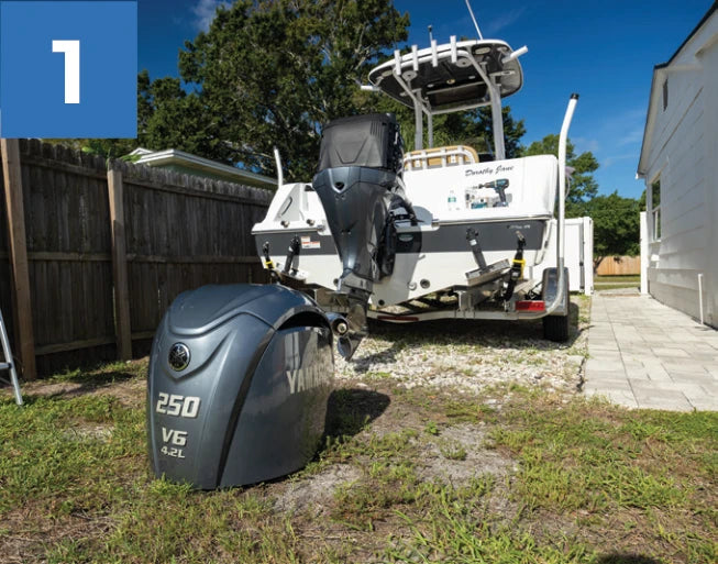
Step 1: Prepare the boat & engine
Remove Cowling to prepare the boat and engine(s) for installation, following the manufacturers’ safety instructions.
Before work: Secure the boat and prevent accidental engine starting using the engine and vessel manufacturers’ safety procedures.
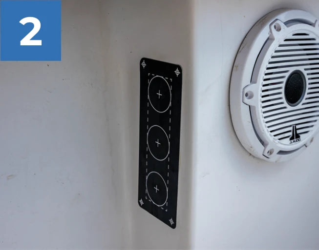
Step 2: Choose the location
Determine the installation location and apply the mounting template. Confirm access and clearance behind it.
Check both sides: Confirm clearance for the full drilling depth, fittings, and hoses. Do not cut until hidden wiring, plumbing, and structural obstructions have been ruled out.
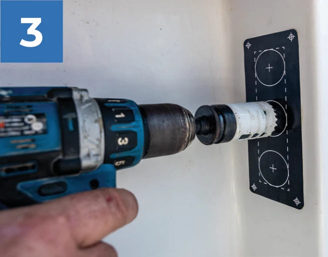
Step 3: Cut the plumbing openings
Cut the plumbing openings using the supplied template.
Guide tip
Use a 1.5″ hole saw, or cut along the template’s cut line.
Before cutting: Verify the template matches your plate and confirm the cutout size. Use suitable eye protection and follow tool and material safety instructions.
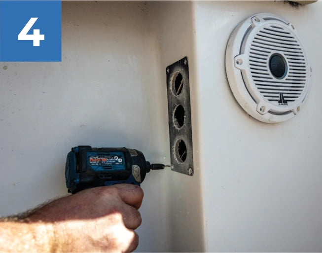
Step 4: Drill the pilot holes
Drill the mounting pilot holes at the marked locations.
Guide tip
For fiberglass 0.125″ thick or less, use a 7/64″ bit. For thicker fiberglass, use a 1/8″ bit. Confirm suitability for your mounting material and fasteners.
Mounting precautions: The bit sizes shown are general guidance. Follow vessel manufacturer requirements for fasteners, mounting support, and sealing drilled or cut surfaces.
Steps 5–8: Route the hose and identify the connection
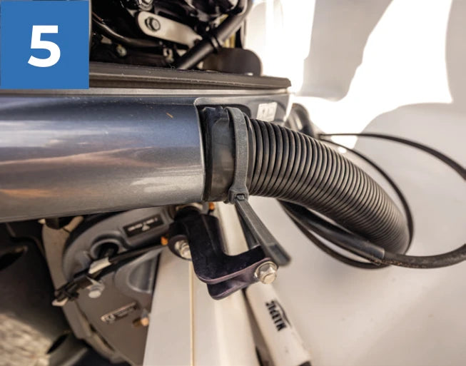
Step 5: Prepare the rigging tube
Prepare the rigging tube(s) for the new hose line(s).
Protect existing rigging: Do not damage or alter existing wiring, fuel lines, steering, or controls. Seek professional assistance if safe access cannot be confirmed.
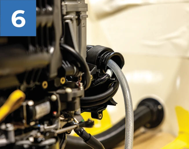
Step 6: Feed the new hose
Feed the new hose line(s) through the rigging tube(s).
Guide tip
Silicone spray is recommended to help feed the hose through the rigging tube. Confirm compatibility with the hose and rigging materials.
Do not force the hose: Stop if routing requires damaging or disturbing existing rigging.
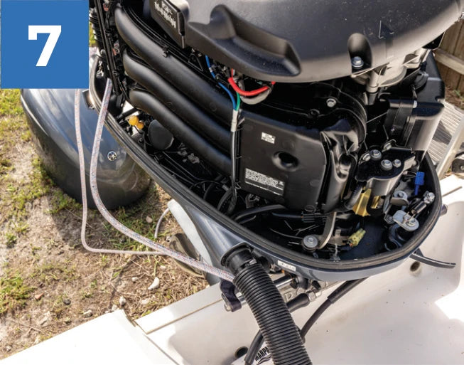
Step 7: Leave enough slack
Leave enough hose to reach inside the engine cowling without tension, including during steering and tilt movement.
Check the full movement range: Keep hoses clear of hot surfaces, sharp edges, and moving parts. Check steering and tilt safely using the manufacturer’s procedure.
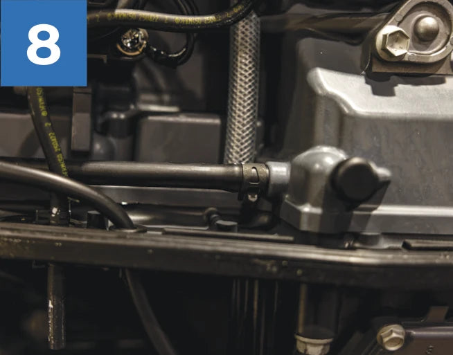
Step 8: Locate the engine’s flush line
Identify the correct flush line inside the cowling. Its location and connection method vary by brand, model, and year.
Engine-specific confirmation is required: Have a qualified marine technician identify the flush line, check-valve arrangement, and any factory reroute provision. Do not bypass or remove a check valve to make this installation fit.
Stop before cutting any engine line
Have a qualified marine technician confirm the correct flush line and connection point, including any check valve or factory reroute provision. Do not cut or modify a line based on these photos alone.
If the connection point or a compatible installation method cannot be confirmed, stop and seek professional installation.
Steps 9–11: Connect at the engine
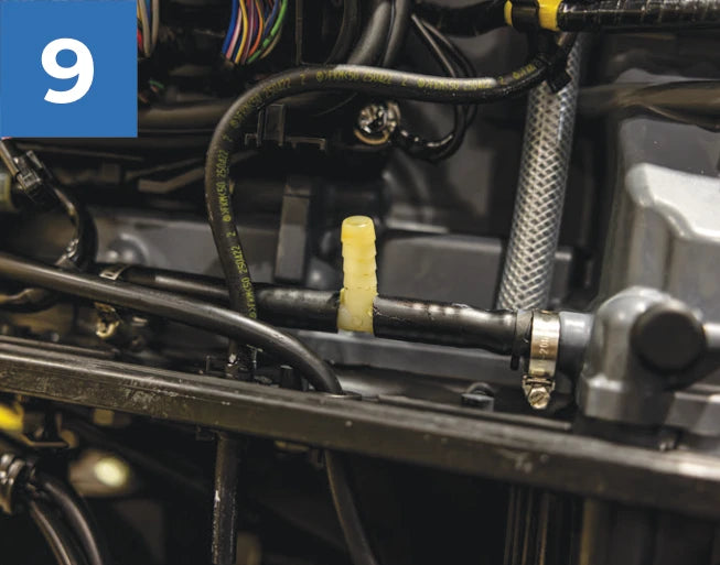
Step 9: Install the tee fitting
Where confirmed appropriate for your engine, cut the identified flush line and insert the compatible tee fitting.
Do not proceed without confirmation: The engine-specific connection method must be established before cutting. A factory-prepared reroute connection may require a different procedure.
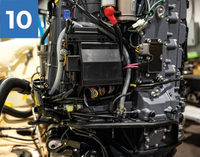
Step 10: Route the hose through the cowling
Route the new flush line through the cowling to the approved connection point.
Protect the hose: Use a manufacturer-approved route. Prevent pinching or chafing where the hose passes through the cowling; do not compromise existing seals or controls.
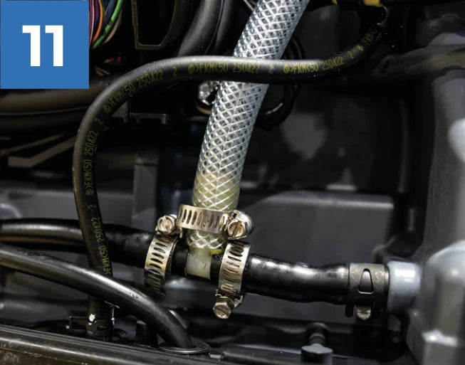
Step 11: Connect to the engine’s flush line
Connect the new hose to the tee fitting and secure the connections with the appropriate hose clamps.
Check each connection: Confirm hose, tee, and clamp compatibility. Follow their fitting and tightening instructions; do not crush or damage the hose or fitting.
Steps 12–13: Route and connect to the plate
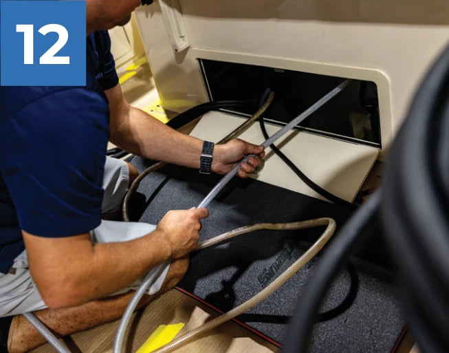
Step 12: Route the hose to the plate location
Feed the new flush line to the chosen location inside the boat.
Secure the route: Protect the hose from heat, abrasion, and moving parts. Maintain access for inspection and avoid sharp bends or kinks.
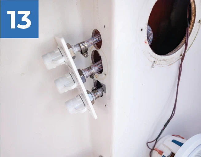
Step 13: Connect to the reroute plate
Connect the new hose line(s) to the plate’s pre-installed barbs and secure with appropriate hose clamps.
Match each engine: Verify each hose connects to its correct labeled outlet. Confirm the hose is fully seated and the clamp is secure before testing.
Before testing
Follow your engine manual’s requirements for engine position and whether the engine must remain off. Use the manufacturer’s specified flushing connection, water supply, and flushing time.
Do not assume the engine can run while connected to a flush port. If the correct procedure is unclear, stop and consult the engine’s authorized service center before testing.
Steps 14–15: Test and complete the installation
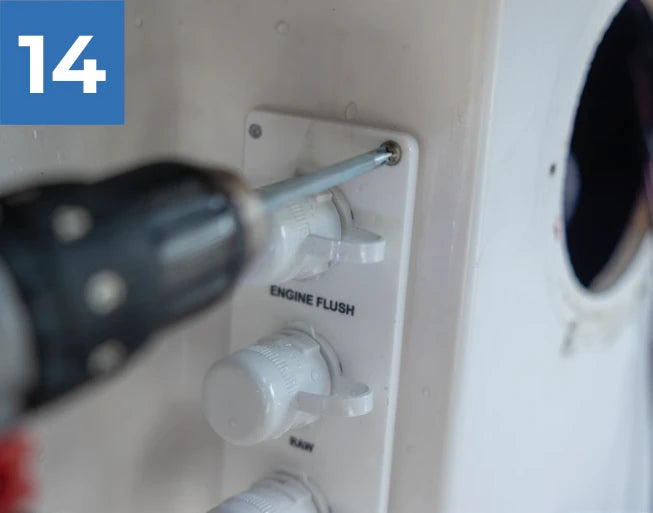
Step 14: Test for leaks, then mount
Test every connection using the engine manufacturer’s flushing procedure. Correct any leaks before mounting the plate.
Before testing
Follow your engine manual’s requirements for engine position and whether the engine must remain off.
If a leak or abnormal condition appears: Stop the test safely using the manufacturer’s procedure. Have the fault corrected and retest before mounting the plate or returning the boat to service.
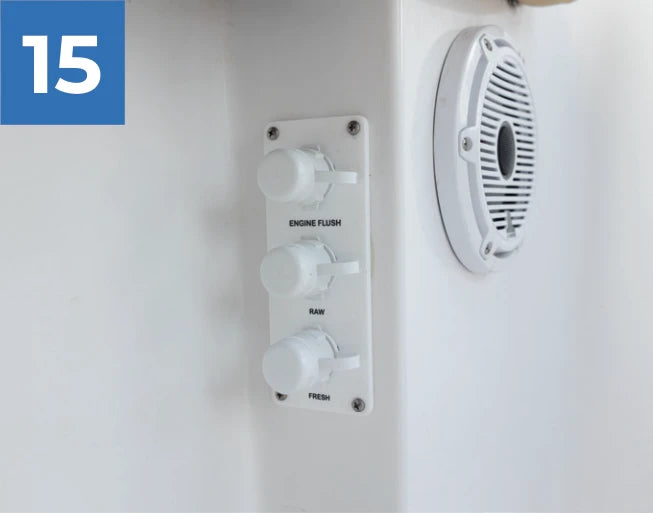
Step 15: Complete the installation
Complete the installation only after successful testing and all final checks. Follow your engine manufacturer’s instructions each time you flush.
Ongoing checks: Inspect hoses, fittings, clamps, and locking caps regularly. If damage, leakage, or restricted movement is found, stop use and have the installation checked by a qualified marine technician.
Before returning to service
Confirm connections are secure, hoses are clear of moving parts, and there is no tension or kinking throughout steering and tilt movement. Refit the cowling and rigging components.
Confirm all required tests are complete, no leaks remain, and the outlet caps are reinstalled and locked. Do not operate the boat if any check is incomplete or any problem remains unresolved.
Unsure about your setup?
For engine-specific plumbing, contact your engine’s authorized service center or a qualified marine technician. For questions about the reroute plate or kit, contact Flushmaster.